 |
|
| |
|
|
业务洽谈:
联系人:张顺平
手机:17727550196(微信同号)
QQ:3003262363
EMAIL:zsp2018@szczkjgs.com
联系人:鄢先辉
手机:17727552449 (微信同号)
QQ:2850985542
EMAIL:yanxianhui@szczkjgs.com
负责人联络方式:
手机:13713728695(微信同号)
QQ:3003207580
EMAIL:panbo@szczkjgs.com
联系人:潘波 |
|
|
| |
|
 |
|
 |
当前位置:首页 -> 方案设计 |
|
|
| IFX007T BLDC马达控制方案 |
|
|
| 文章来源:永阜康科技 更新时间:2019/8/5 9:48:00 |
|
infineon公司的IFX007T是集成了大电流半桥的马达驱动器,是工业和多用途NovalithIC™系列中一员,一个封装内包含有P沟高边MOSFET和N沟低边MOSFET以及集成的驱动器集成电路,它具有逻辑电平输入,带电流检测的诊断,转换速率调整,死区时间产生以及超温保护,欠压保护,过流保护和短路保护等特性,很容易和微控制器接口.通路电阻最大为12.8 mΩ @ 25℃ (typ.10.0 mΩ @ 25℃),高边电阻最大为6.5 mΩ @ 25℃ (typ.5.3 mΩ @ 25℃),低边电阻最大为6.3 mΩ @ 25℃ (typ. 4.7mΩ @ 25℃),限流电流最大为55A,工作电压高达40 V, RoHS兼容,满足JESD47I规范,主要用在自动化,家用电器,机器人和医疗电子以及电动工具,小型机器人,无人机,真空吸尘器,医用马达,医院病床,3D打印机,电风扇,电泵等.本文介绍了IFX007T主要特性,框图和应用电路,以及马达控制板主要特性,电路图,PCB设计图.
The IFX007T is an integrated high current half bridge for motor drive applications. It is part of the Industrial &Multi PurposeNovalithIC™ family containing one p-channel high-side MOSFET and one n-channel low-sideMOSFET with an integrated driver IC in one package. Due to the p-channel high-side switch the need for acharge pump is eliminated thus minimizing EMI. Interfacing to a microcontroller is made easy by theintegrated driver IC which features logic level inputs, diagnosis with current sense, slew rate adjustment, deadtime generation and protection against overtemperature, undervoltage, overcurrent and short circuit.
The IFX007T provides a cost optimized solution for protected high current PWM motor drives with very lowboard space consumption.
IFX007T主要特性:
• Path resistance of max.12.8 mΩ @ 25℃ (typ.10.0 mΩ @ 25℃)
High side: max. 6.5 mΩ @ 25℃ (typ. 5.3 mΩ @ 25℃)
Low side: max. 6.3 mΩ @ 25℃ (typ. 4.7mΩ @ 25℃)
• Enhanced switching speed for reduced switching losses
• Capable for high PWM frequency combined with active freewheeling
• Switched mode current limitation for reduced power dissipation in overcurrent
• Current limitation level of 55 A min.
• Status flag diagnosis with current sense capability
• Overtemperature shutdown with latch behavior
• Undervoltage shutdown
• Driver circuit with logic level inputs
• Adjustable slew rates for optimized EMI
• Operation up to 40 V
• Green Product (RoHS compliant)
• JESD47I Qualified
IFX007T目标应用:
The features of the NovalithICTM IFX007T make it an ideal half bridge for industrial & consumer motor drive for automation, home appliances, robotics, and medical applications: power tools, small robotics, drones, vacuum cleaners, medical motors, hospital beds, 3D printers, fans, pumps, and many more.

图1.IFX007T框图
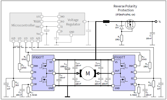
图2. IFX007T应用电路:两个IFX007T H桥
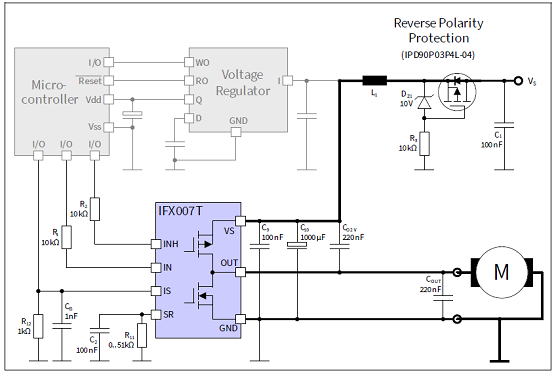
图3. IFX007T应用电路:一个IFX007T半桥(负载接地)
马达控制板
The Motor Control Shield adds powerful motor control to the Arduino projects. The shield can be controlledwith the general logic IO-Ports of a microcontroller. Either an Arduino Uno or the XMC4700 Relax Kit fromInfineon can be used as the master.
On board of the Motor Control Shield are three IFX007T NovalithICTM. Each is featuring one P-channel high sideMOSFET and one N-channel low side MOSFET with an integrated driver IC in one package. Due to the P-channelhigh side switch a charge pump is not needed.
The IFX007T half-bridge is easy to control by applying logic level signals to the IN and INH pin. When applying aPWM to the IN pin the current provided to the motor can be controlled with the duty cycle of the PWM. With anexternal resistor connected between the SR pin and GND the slew rate of the power switches can be adjusted.
The Motor Control Shield can be easily connected to any Arduino board or the XMC4700 Relax Kit via headers.
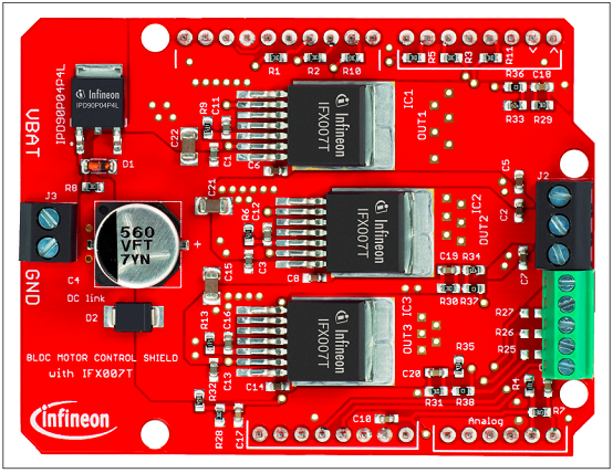
图4.马达控制板外形图
马达控制板主要特性:
• An Arduino Uno, XMC4700 Relax Kit, or similar board connected to the shield can control the three halfbridgesvia the general IO pins.
• Brushed DC Motor Control up to 250 W continuous load
- 8–24 V nominal input voltage (max. 6–40 V)
- Average motor current 30 A restricted due to the limited power dissipation of the PCB (IFX007T currentlimitation @ 55 A min.)
• Drives either one brush/less DC motor, one brushed bi-directional DC motor or three uni-directional DCmotors.
• Capable of high frequency PWM, e.g. 25 kHz
• Adjustable slew rates for optimized EMI by changing external resistor
• Driver circuit with logic level inputs
• Status flag diagnosis with current sense capability
• Protection e.g. against overtemperature and overcurrent
• Reverse polarity protection with IPD90P04P4L
• Further comments:
- Due to limited performance caused by the PCB layout, we recommend our customers to remove thecapacitance C5 for high frequency applications. It is only layout related, not refer to the device.
- The size of the DC-link capacity (C4 in schematic) with 560 μF is for most applications sufficient. But forhigh current applications, we recommend our customers to follow the design rule in our applicationnote and replace the DC-link cap with a bigger one.
- Due to the limited area of the PCB and the small DC-link cap, the demoboard shouldn’t be used forshort circuit test.
- This demoboard is designed for both sensorless applications and the application with Hall sensor. Butfor the application with sensor, please remove R36/R37/R38 and solder R18/R19/R20/R21/R22/R23/R25/R26/R27.
- Due to the limited pinout of the Arduino shield all IS pins of the three devices are connected together.According to different applications the value of R4 could be adjusted to achieve a better current sense performance.
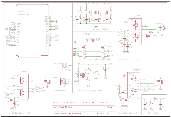
图5.马达控制板电路图

图6.IFX007T热RC网络电路图
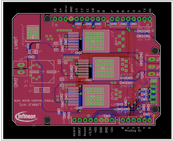
图7.马达控制板PCB设计图:Arduino和IFX007T
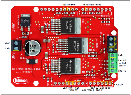
图8.马达控制板PCB设计图:连接器
|
|
| |
| |
|
|
|